Alternative Raspberry Pi Board
For several months now, it has become impossible to buy a Raspberry Pi from official resellers, this situation has a very heavy impact on the world of makers and industries, also on our business.
After weeks of searching we have found an alternative Single Board Computer compliant with a part of our boards ROCK 4 SE.
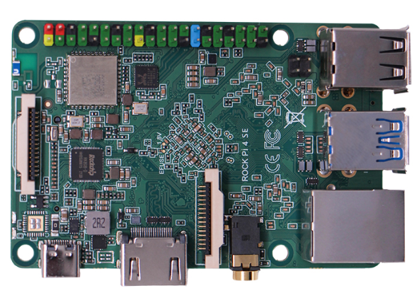
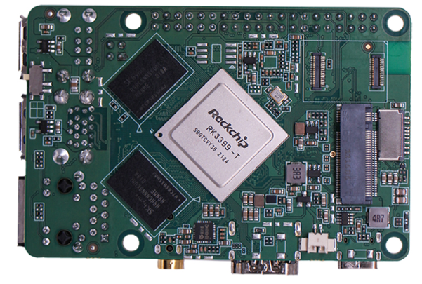
ROCK 4 SE is a Single Board Computer (SBC) in an ultra small form factor that offers class leading performance and an extensive range of expansion ports . The ROCK 4 SE offers professionals, industrial OEMs, IoT enthusiasts, hobbyists, PC DIY enthusiasts and makers a reliable and extremely capable platform for building and tinkering their ideas into reality. ROCK 4 SE is available in 4GB LPDDR4 RAM option.
The complete features are described on official wiki
| Processor | 64bits hexa core processor Rockchip RK3399-T Dual Cortex-72, frequency 1.5GHz with qual Cortex-A53, frequency 1.0GHz Mali T860MP4 gpu, support OpenGL ES 1.1/2.0/3.0/3.1/3.2, Vulkan 1.0, Open CL 1.1 1.2, DX11. |
| Memory | LPDDR4 64bit dual channel LPDDR4@3200Mb/s, 1GB/2GB/4GB optioal |
| Storage | eMMC connector, μSD card (μSD slot supports up to 256 GB μSD card), M.2 SSD (M.2 connector supports up to 2T M2 NVME SSD) |
| Display | Standard HDMI 2.0 up to 4k@60, MIPI DSI 2 lanes via FPC connector. HDMI and MIPI DSI can work at the same time, support mirror mode or extend mode. |
| Audio | 3.5mm jack with mic HD codec that supports up to 24-bit/96KHz audio. |
| Camera | MIPI CSI 2 lanes via FPC connector, support up to 800 MP camera(1mm pitch connector). |
| Wireless | 802.11 ac wifi, BT 5.0 with on board or external antenna |
| USB | USB 3.0 OTG X1, hardware switch for host/device switch, upper one USB 3.0 HOST X1, dedicated USB 3.0 channel, lower one USB 2.0 HOST X2 |
| Ethernet | GbE LAN with Power over Ethernet (PoE) support additional HAT is required for powering from PoE |
| IO | 40-pin expansion header 2 x UART 2 x SPI bus 3 x I2C bus 1 x PCM/I2S 1 x SPDIF 2 x PWM 1 x ADC 6 x GPIO 2 x 5V DC power in 2 x 3.3V DC power in |
| Others | RTC, RTC battery connector for time backup(optional) |
| Power | USB PD, support USB Type C PD 2.0, 9V/2A, 12V/2A. Qualcomm® Quick ChargeTM: Supports QC 3.0/2.0 adapter, 9V/2A, 12V/1.5A |
| Size | 85mm x 54mm |
If you check the Rock 4 board pinout carefully, you can discover that it is not fully complaint with Raspberry Pi, our boards Dual Can requires the following peripherals:
- SPI with 2 Chip select on pins 19, 21, 23, 24 and 26
- I2C for RTC on pins 3 and 5
- 2 interrupts on pins 15 and 22
On the following table you can see that the second SPI chip select is not available on pin 26 for ROCK 4 SE board.
| ROCK 4 SE | RPI | PIN L | PIN R | RPI | ROCK 4 SE |
| 3V3 | 3V3 | 1 | 2 | 5V | 5V |
| SDA_I2C7 / GPIO2_A7 | SDA_I2C1 / GPIO2 | 3 | 4 | 5V | 5V |
| SCL_I2C7 / GPIO2_B0 | SCL_I2C1 / GPIO3 | 5 | 6 | GND | GND |
| GPIO2_B3 | GPIO4 | 7 | 8 | UART0_TXD / GPIO14 | UART2_TXD / GPIO4_C4 |
| GND | GND | 9 | 10 | UART0_RXD / GPIO15 | UART2_RXD / GPIO4_C3 |
| GPIO4_C2 | GPIO17 | 11 | 12 | GPIO18 | GPIO4_A3 |
| GPIO4_C6 | GPIO27 | 13 | 14 | GND | GND |
| GPIO4_C5 | GPIO22 | 15 | 16 | GPIO23 | GPIO4_D2 |
| 3V3 | 3V3 | 17 | 18 | GPIO24 | GPIO4_D4 |
| SPI1_TXD / GPIO1_B0 | SPI0_MOSI / GPIO10 | 19 | 20 | GND | GND |
| SPI1_RXD / GPIO1_A7 | SPI0_MISO / GPIO09 | 21 | 22 | GPIO25 | GPIO4_D5 |
| SPI1_CLK / GPIO1_B1 | SPI0_SCLK / GPIO11 | 23 | 24 | SPI0_CE0 / GPIO08 | SPI1_CSn / GPIO1_B2 |
| GND | GND | 25 | 26 | SPI0_CE1 / GPIO07 | ADC_IN0 |
| GPIO2_A0 | ID_SD / GPIO00 | 27 | 28 | ID_SC / GPIO01 | GPIO2_A1 |
| GPIO2_B2 | GPIO05 | 29 | 30 | GND | GND |
| GPIO2_B1 | GPIO06 | 31 | 32 | GPIO12 | GPIO3_C0 |
| GPIO2_B4 | GPIO13 | 33 | 34 | GND | GND |
| GPIO4_A5 | GPIO19 | 35 | 36 | GPIO16 | GPIO4_A4 |
| GPIO4_D6 | GPIO26 | 37 | 38 | GPIO20 | GPIO4_A6 |
| GND | GND | 39 | 40 | GPIO21 | GPIO4_A7 |
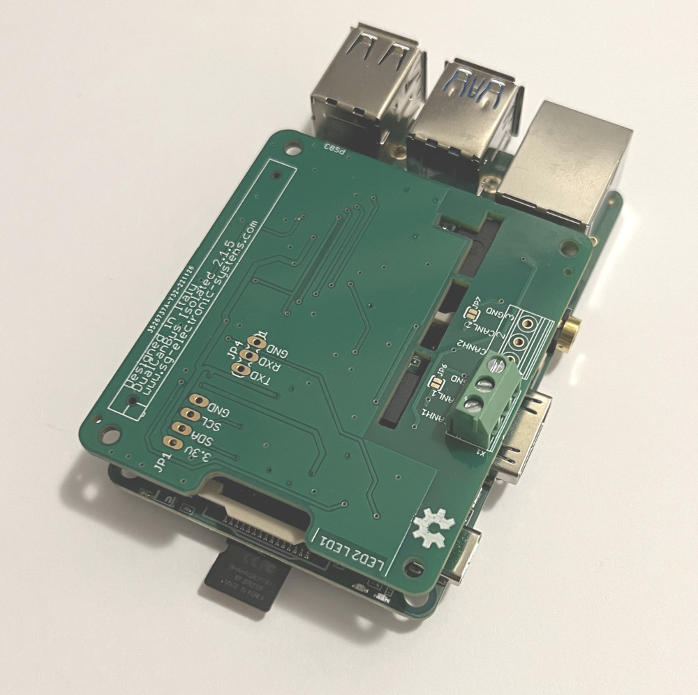
The result is that only one can bus interface can work…
Software configuration
It is possible to install 3 different Operating Systems: Android, Debian and Ubuntu Server.

For our test we have downloaded Ubuntu Server 20, follow the official wiki for SD card preparation.
Login with user rock and password rock
Modify file /boot/hw_intfc.conf. Set “on” to enable the optional hardware interfaces while set “off” to disable.
sudo nano /boot/hw_intfc.confEnable the following overlays:
intfc:i2c7=on
intfc:spi1=on
intfc:dtoverlay=mcp2515-can0-SG
Save and exit and reboot the board with sudo reboot
Overlay customization
The Ubuntu image contains the following overlay dtbo files (dts file download)
/boot
   |--rockpi-4b-linux.dtb
   |--hw_intfc.conf
   |--overlays
     |--at24c02.dtbo
     |--console-on-ttyS4.dtbo
     |--console-on-ttyS2.dtbo
     |--cpufreq.dtbo
     |--devspi1.dtbo
     |--devspi2.dtbo
     |--imx219.dtbo
     |--pcie-gen2.dtbo
     |--raspberrypi-7-inch-lcd.dtbo
     |--rk3399-usb-host.dtbo
     |--rk3399-usb-otg.dtbo
     |--rock-4c-plus-raspberrypi-7inch-touchscreen.dtbo
     |--rock-4c-plus-radxa-display-8hd.dtbo
     |--rock-4c-plus-radxa-display-10hd.dtbo
     |--spi1-waveshare35c.dtbo
     |--spi1-waveshare35b-v2.dtbo
     |--spi1-flash.dtbo
     |--spi1-mcp2515-can0.dtbo
     |--two-color-led.dtbo
     |--w1-gpio4-30.dtbo
The spi1-mcp2515-can0.dtbo is not correct for the following problem: clock-frequency = <12000000>;
Our board works with a 16 Mhz oscillator, then we must generate a custom file mcp2515-can0-SG.dtbo.
/* This devicetree overlay is INT pin 15 is GPIO4_C5 --> 4 A= 0, B = 1, C=2, D=3
* Pin is 4 C*8+5 ---> rockchip,pins = <4 21 0 &pcfg_pull_none>;
* Device tree overlay for mcp251x/can0
*/
/dts-v1/;
/plugin/;

/ {
        compatible = "rockchip,rockpi","rockchip,rk3399", "rockchip,rk3399-pinctrl";

        fragment@0 {
                target = <&pinctrl>;

                __overlay__ {
                        mcp2515_int_pin: mcp2515_int_pin {
                                rockchip,pins = <4 21 0 &pcfg_pull_none>;
                        };
                };
        };

        fragment@1 {
                target-path = "/";
                __overlay__ {
                        can_mcp2515_osc: can-mcp2515-osc {
                                compatible = "fixed-clock";
                                clock-frequency = <16000000>;
                                #clock-cells = <0>;
                        };
                };
        };

        fragment@2 {
                target = <&spi1>;

                __overlay__ {
                        status = "okay";
                        max-freq = <10000000>;
                        #address-cells = <1>;
                        #size-cells = <0>;

                        can_mcp2515: can-mcp2515@0 {
                                status = "okay";
                                compatible = "microchip,mcp2515";
                                reg = <0>;
                                interrupt-parent = <&gpio4>;
                                interrupts = <21 2>;
                                spi-max-frequency = <10000000>;
                                clocks = <&can_mcp2515_osc>;
                                vdd-supply = <&vcc3v3_sys>;
                                xceiver-supply = <&vcc3v3_sys>;
                                pinctrl-names = "default";
                                pinctrl-0 = <&mcp2515_int_pin>;
                        };
                };
        };
};
For dtbo generation you must install the device tree compiler
sudo apt update
sudo apt install device-tree-compiler
sudo apt install can-utils
cd /boot/overlays
sudo /usr/bin/dtc -I dts -O dtb -o mcp2515-can0-SG.dtbo -I dts mcp2515-can0-SG.dts
sudo reboot
After the board startup use the following command to start can0 interface
sudo ip link set can0 up type can bitrate 1000000
ifconfig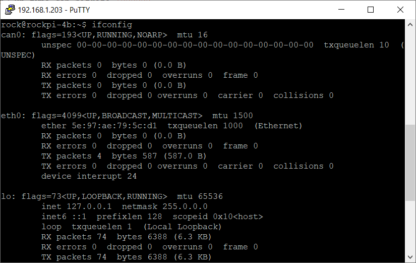
CAN BUS Test
Test 1: Raspberry Pi CAN TX —-> Rock Pi CAN RX
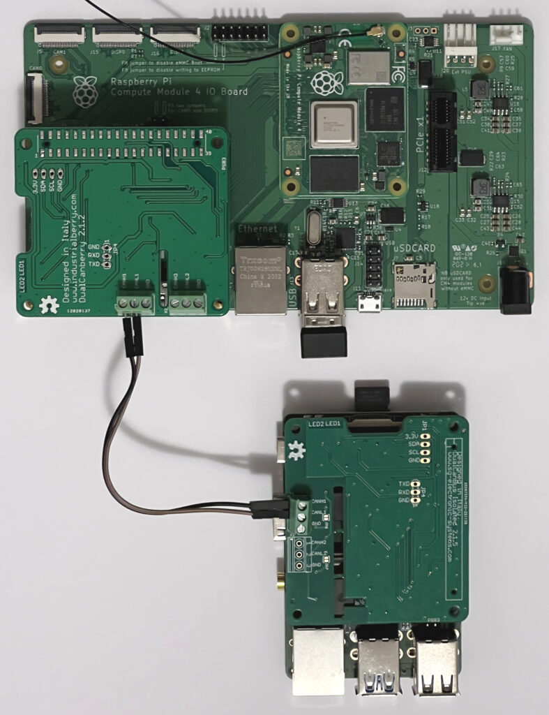
Raspberry Pi run the command
cangen can1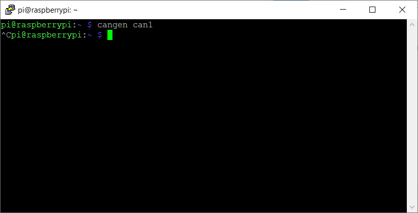
instead on Rock Pi run
candump can0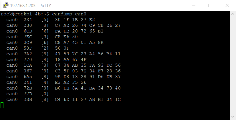
Test 2: Rock Pi CAN TX —-> Raspberry Pi CAN RX
Rock Pi run the command
cangen can0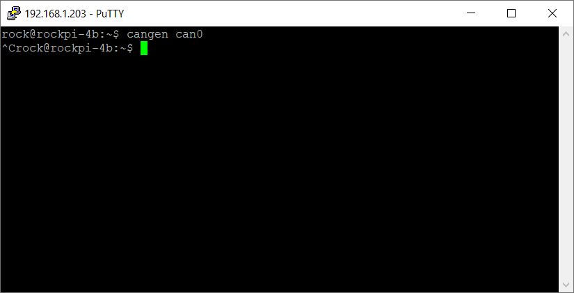
Raspberry Pi run the command
candump can1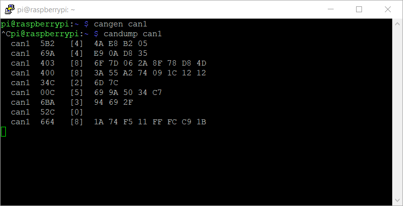
If the device trees on both boards are correctly configured and the can adapters are correctly connected you can see the message log under candump terminal.
I2C DETECT
It is possible to detect the RTC with i2cdetect command
rock@rockpi-4b:~$ sudo i2cdetect -y 7
     0  1  2  3  4  5  6  7  8  9  a  b  c  d  e  f
00:          -- -- -- -- -- -- -- -- -- -- -- -- --
10: -- -- -- -- -- -- -- -- -- -- -- -- -- -- -- --
20: -- -- -- -- -- -- -- -- -- -- -- -- -- -- -- --
30: -- -- -- -- -- -- -- -- -- -- -- -- -- -- -- --
40: -- -- -- -- -- -- -- -- -- -- -- -- -- -- -- --
50: -- 51 -- -- -- -- -- -- -- -- -- -- -- -- -- --
60: -- -- -- -- -- -- -- -- -- -- -- -- -- -- -- --
70: -- -- -- -- -- -- -- --
Leave a Reply